The Santa Barbara Instruments Group (SBIG) ST7E
camera is designed especially for amateur astronomers to take images with small
telescopes. It has a Kodak KAF-0401E charged coupled device (CCD) detector with
![]() pixels, each
pixels, each ![]() square. (A
square. (A ![]() or micron is
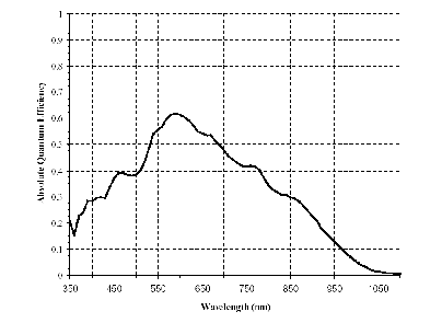
0.001 mm.) The detector is sensitive from the near ultraviolet around 350 nm to
the infrared around 1100 nm (or 1.1
or micron is
0.001 mm.) The detector is sensitive from the near ultraviolet around 350 nm to
the infrared around 1100 nm (or 1.1 ![]() ). Typically the detector is
operated well below room temperature in order to reduce the thermal dark signal.
With the electronics that interface this sensor to the computer, one digital
unit (so-called analog-to-digital unit or ADU) corresponds to 2.3 electrons
in the sensor. Each incident photon that is detected creates a photoelectron,
and the probability of a single photon being detected is about 65% at the
maximum of the quantum efficiency curve. At
). Typically the detector is
operated well below room temperature in order to reduce the thermal dark signal.
With the electronics that interface this sensor to the computer, one digital
unit (so-called analog-to-digital unit or ADU) corresponds to 2.3 electrons
in the sensor. Each incident photon that is detected creates a photoelectron,
and the probability of a single photon being detected is about 65% at the
maximum of the quantum efficiency curve. At ![]() there will be
about 1 electron per pixel per second due to the thermal dark current, that is,
electrons which are freed from their potential well by their own kinetic energy
rather than by the energy of the incident photon.
there will be
about 1 electron per pixel per second due to the thermal dark current, that is,
electrons which are freed from their potential well by their own kinetic energy
rather than by the energy of the incident photon.
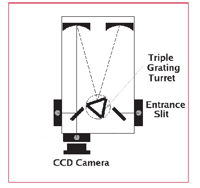
The detector is at the focus of a small spectrograph which forms an image of a spectrum on the CCD. The signal from each pixel of the CCD is proportional to the number of photons that fall at that point during the exposure. Different positions along the CCD correspond to different wavelengths of light, so the image you will see reveals the spectrum of the light source dispersed across the detector.
The Acton Research 300i spectrograph covers from 180 to 1400 nm,
resolves 0.1 nm, and sets to a selected wavelength
to within ![]() 0.2 nm. It is a Czerny-Turner design with two f/4
aspheric mirrors, one
to collimate the light that strikes the grating, and the other to focus the
spectrum. By making the mirrors aspheric (not spherical)
and by a design that optimizes where the mirrors and the grating are located, it
is possible to have very good focus and image quality across the flat surface of
the CCD.
There are three gratings in a turret that is rotated by a stepping
motor. The selection of grating and wavelength is controlled by this
motor using simple commands to the computer in the spectrograph.
0.2 nm. It is a Czerny-Turner design with two f/4
aspheric mirrors, one
to collimate the light that strikes the grating, and the other to focus the
spectrum. By making the mirrors aspheric (not spherical)
and by a design that optimizes where the mirrors and the grating are located, it
is possible to have very good focus and image quality across the flat surface of
the CCD.
There are three gratings in a turret that is rotated by a stepping
motor. The selection of grating and wavelength is controlled by this
motor using simple commands to the computer in the spectrograph.
Each pixel of the CCD covers ![]() in the focal plane of the
spectrograph. The spectrograph disperses light across the focal plane with
in the focal plane of the
spectrograph. The spectrograph disperses light across the focal plane with
![]() (nm/mm) as shown in the table below, and accordingly each
(nm/mm) as shown in the table below, and accordingly each
![]() pixel covers
pixel covers ![]() (nm). Since there are 765 pixels across the
width of the CCD, this scale determines how much of the spectrum is recorded in a single
exposure. The table shows that to record detail it is best to use a finely
grooved grating, but to record as much of the spectrum as possible it is better
to use fewer grooves/mm. Also, with detector elements
(nm). Since there are 765 pixels across the
width of the CCD, this scale determines how much of the spectrum is recorded in a single
exposure. The table shows that to record detail it is best to use a finely
grooved grating, but to record as much of the spectrum as possible it is better
to use fewer grooves/mm. Also, with detector elements ![]() across, and the entrance slit imaged at each wavelength on the
detector, the instrument will have its best resolution when the slit is set
at
across, and the entrance slit imaged at each wavelength on the
detector, the instrument will have its best resolution when the slit is set
at ![]() as well.
as well.
| Diffraction Gratings | |||||
| ID | Grooves | Blaze |
Coverage | ||
|
|
nm | nm/mm | nm/pixel | nm | |
| 1 | 2400 | 240 | 1.389 | 0.0125 | 9.56 |
| 2 | 1200 | 500 | 2.778 | 0.0250 | 19.1 |
| 3 | 300 | 1000 | 11.11 | 0.0999 | 76.4 |